Lesson 4 - Freeform Modeling
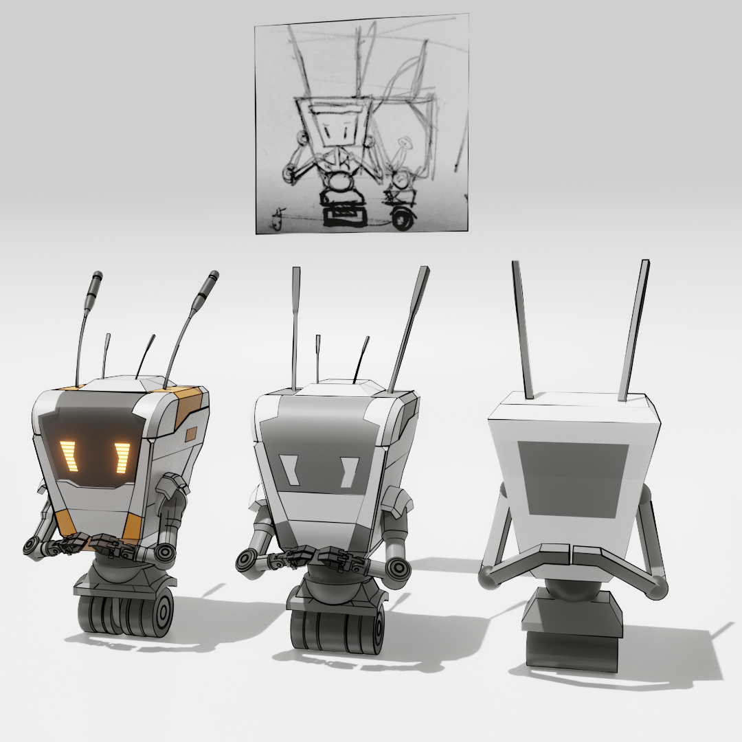
In this lesson we will be mainly talking about Subdivision Surface Modelling. But the Assignment 4 will not use the techniques discusses below. Instead we will use everything we learned up to lesson 3 to flesh out a concept of a Robot. That we will later make production ready with the techniques below.
Subdivision Surface Modelling
To get smooth looking surfaces instead of the faceted or blocky representations of objects we have been creating until now we can leverage the Subdivision Surface Modifier. The subdivision surface algorithm will create additional geometry for us, while we only have to edit a simple mesh (often called control cage).
Algorithm - What is happening under the hood
The subdivision surface algorithm is a recursive algorithm that refines our input mesh by subdividing it and creating new vertices, edges and faces. Every implementation of the subdivision surface algorithm has an Iterations Parameter which will enable us to set the number of recursions and create smoother and smoother looking meshes by subdividing it more and more.
During the refinement stage the shape of our object can change very drastically, we will discuss ways to control the shape in the section below.
Cube Mesh getting subdivided from 0 to 5 Iterations.
Warning
A big limitation of the Subdivision surface modelling approach is that the algorithm only works predictably well on quadrilaterial faces I.e faces with 4 vertices. Using triangles or N-gons will result in artifacts, bumps and pinches in the smoothed surface and can also lead to the mesh totally losing its form in some places.
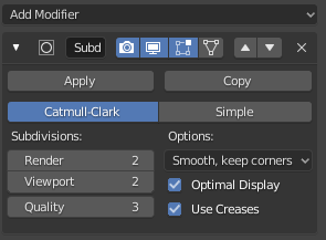
Subdivison Surface Modifier
To create a Subdivision Surface Model in Blender you have to add a Subdivision Surface Modifier to the mesh you want to subdivide. You can also quickly add a Subd-Modifier and/or setting its Iterations Parameter by pressing Hotkey: Ctrl + 1,2,3,4,5 (Number sets the Iterations Parameter)
- Blender Manual Link:
Topology for subdivision surfaces
During the subdivision/refinement the shape of our object can change quite drastically. How much it changes and which features of the input shape are being smoothed and which aren’t depends on how the mesh is constructed. The structure of a Mesh, I.e how it’s vertices, edges and faces are laid out is often called its Topology.
A mesh/control cage that works will with the subdivision surface algorithm has good topology/edgeflow, I.e the way in which its edgeloops and edgerings are laid out create no problems for the subdivsion surface algorithm.
Subdivions surface mesh with its control cage edges shown in a smoothed Optimal Display mode.
Supporting/Holding Edges (Rule of Three)
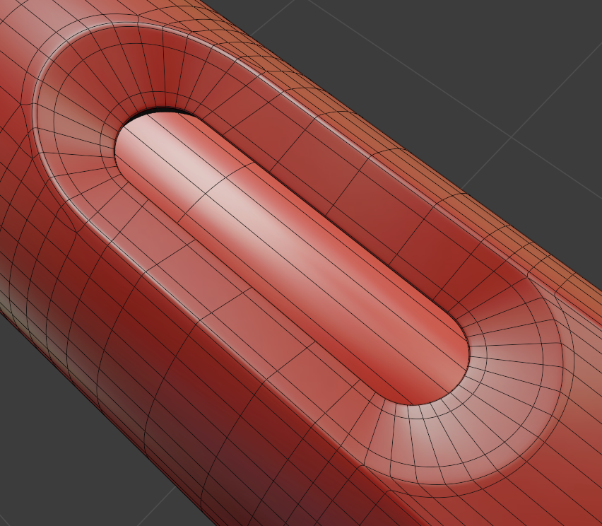
How much the geometry is being smoothed and pulled away from its control cage depends on how far apart the edges of the control cage are. The farther apart they are the more smoothing happens and the closer they are the more the shape of the control cage stays the same.
For optimal control of each edge in your control cage you want a supporting or holding edge on each side of it. With this set of 3 edges you can control how the mesh is getting smoothed on each of the two sides of the edge defining your base form. This is sometimes called the Rule of Three.
- Rule of Three:
- Have a supporting/holding edge on either side of your form/shape defining edge
Simple geometry showing how edge distance changes how the subd-algorithm smoothes the mesh.
Working with a support edge on either side of your base or formgiving edge has other benefits as well. Which we will discuss in the section on Collapsing/Terminating Edges.
Border Edgeloops
To be able to place supporting or holding edges close to our formgiving/shaping edges we need to construct our Edgeloops and Edgerings in a specific manner. One of those are the socalled Borderloops. Borderloops form a loop of connecting edges that follow the form of a specific feature we want to cut into our mesh or the border/outline of our shape.
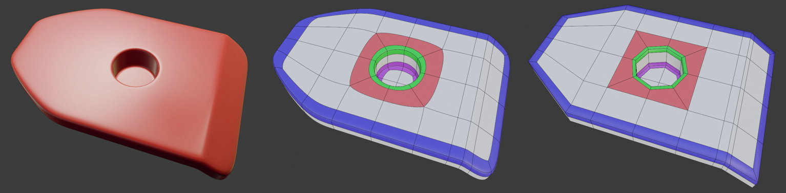
Left to right: Subdivided Mesh, its smoothed (optimal display) and unsmoothed control cage with borderloops highlighted in different colors. Every form giving edge als has supporting edges.
Collapsing/Terminating Edges
There will be areas in our mesh where we need more or less edges, so we will have to get rid of or add in some edges. Because we want our mesh to consist mostly of quadrilaterials (Quads) to prevent problems with the subdivision surface algorithm we can’t just simply remove or add them where/how we want to.
This problem is very common and we have already worked out solutions for most cases. The graphic below shows the most common termination of edges, but there will be situations where you will have to improvise and fix your edgeflow yourself, without any help. The more you model with subdivision surfaces the better you will get at it.
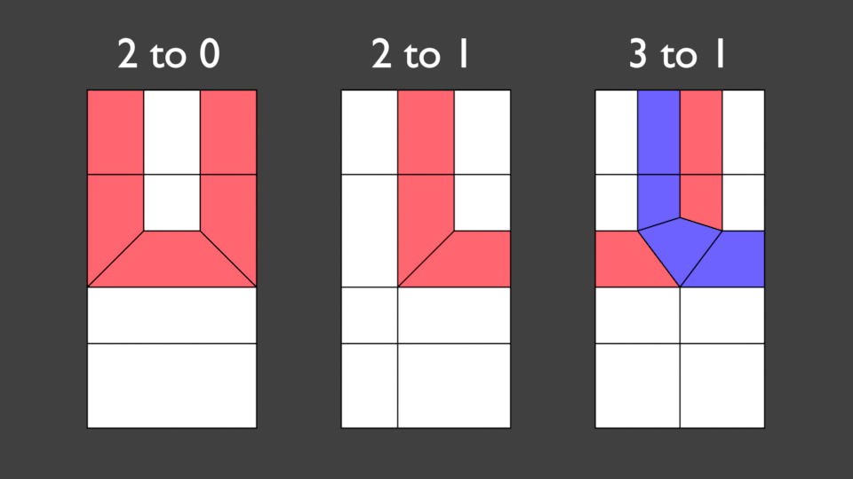
3 ways of terminating edges, while keeping everything in quads.
Additional Tools for Subdivions Surface Modelling
Spotting problems and Artifacts
When we want to create very smooth surfaces we need to be able to spot problem areas where there are bumps, pinching or dimples in our surface. These things are very hard to spot on a dull surface or with the default material that is on our mesh when we model in the Solid View Mode.
Luckily we can apply a range of “materials” very quickly to all our objects in the 3D Viewport by using Matcaps. Very shiny matcaps make it easy to find problematic areas on our subdivision surface models.
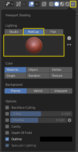
You can enable Matcaps on the top right hand side of the 3D Viewport
- Click on the Downward triangle arrow to the right of the Viewport Shading mode buttons.
- Click on the Matcap button
- Change the current Matcap by clicking on the Sphere below the Matcap button to open a list of matcaps to selected from.
Tip
Sadly some very useful matcaps were dropped from the list of available matcaps with the release of Blender 2.8. I provide a zip-archive of the in my opinion most useful matcaps for subdivision surface modelling.
- Download:
Subdivsion-Surface-Matcaps
After you unpacked the archive you can add them to your matcaplist by:
- Opening Preferences with Edit > Preferences… or Hotkey: F4 > Preferences…
- Navigate to the Lights section by clicking on the button on the left.
- Clicking on the Install button in the Matcap Rollout section
- Using the Filebrowser to select all Matcaps you want to add and confirming with the button on the bottom right.
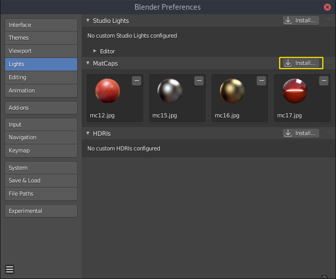
Blender Preferences Lights section showing my favorite matcaps already imported in the MatCaps Rollout.
Remove/Dissolve Edge
Hotkey: Ctrl + X
The Dissolve Selection Command lets you remove edges and their corresponding vertices quickly. This operation is very useful if you want to change the topology of your mesh by rerouting some edges.
Connect Vertex Path
Hotkey: J
This tool lets you create a cut between 2 selected vertices. It will use the shortest path between them to make the cut. This tool is excellent for quick short cuts for rerouting edgeflow in a mesh.

Shrink/Fatten
Hotkey: Alt + S
Shrink/Fatten moves the selected vertices along their vertex normals and is a great addition to the normal scale tool. In cases where scaling or moving of multiple vertices doesn’t do the job the Shrink/Fatten Operator often helps a great deal.
Joining Objects and Separating Meshes
- Join | Hotkey: Ctrl + J
- Separate | Hotkey: P
In some cases we want to combine two separate objects in to one or split subparts of our mesh off into another object.
We can combine/join two objects together by selecting them and then pressing Hotkey: Ctrl + J in Object Mode.
We can split parts of our mesh off into a separate object by selecting the faces in Edit Mode and then pressing Hotkey: P >> Selection to part the mesh into two objects.
LoopTools
Hotkey: RMouse-click (Edit Mode) [After you activated the Addon]
The LoopTools addon has a range of useful tools that help us to create shapes in our mesh or help us align a selection of vertices quickly. Its most useful tool is the Circle Command which transforms the elements of the current selection into a circle.
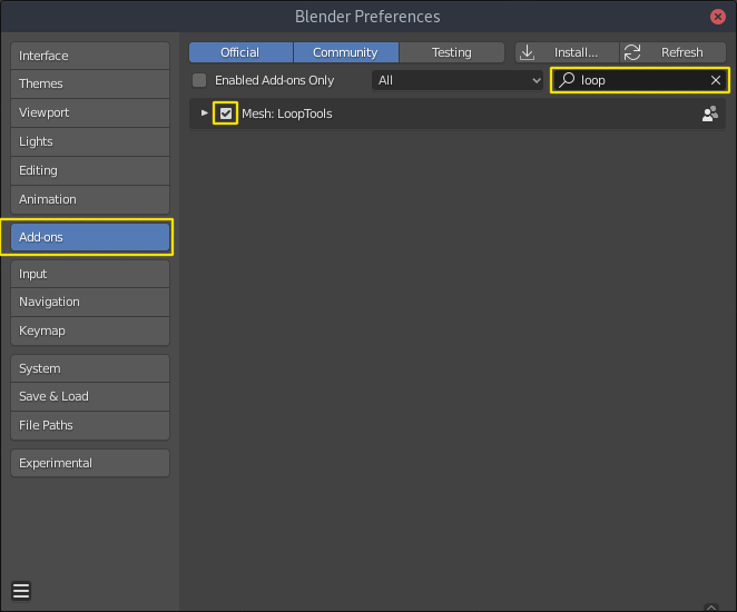
You can activate the addon like this:
- Edit >> Preferences… or Hotkey: F4 >> Preferences…
- Open the Addons tab on the left hand side
- Use the Search textinput on the top right with the query loop to find the addon
- Activate it by ticking its checkbox
Materials
PBR Model (Physically Based Rendering)
The PBR model was created to better simulate real life materials and make it easier for the artist to create physically accurate representations of surfaces. It was adopted around 2013 and is very widespread and used in almost any 3D software and game engine out on the market currently. It replaced the old Specular/Glossiness Model that we will briefly look at later.
Even though its name doesn’t suggest it, you can also create materials and looks with it that arent physically correct. The material model can also be used for heavily stylized or cartoony looks.
The Blender Principled BSDF is a Shader that implements Pixar’s Principled Shader and builds on the PBR Model.
- The PBR Model in its most basic form includes the following parameters/slots:
- Albedo/Basecolor
- Specular
- Roughness
- Metallness/Metallic
Albedo/Basecolor
Albedo is the basecolor of you Material, it defines the color of the object when it is hit with very diffused light. If a map/texture is used it shouldn’t contain any lighting information (No Shadows or Highlights).
Good values for Albedo/Basecolor are in a specific range, it is recommended to stay away from very dark values (< 0.05-0.1) and very bright values (> 0.8). It is also good practise to not use overly saturated colors, very bright saturated colors are not that common in the real world.
Specular
The Specular parameter control how much a surface reflects light. The principled BSDF has a default value of 0.5 which is accurate for a wide variety of materials. An example for a material with low specular would be rubber while water, glass or diamonds have a very high specular value.
Roughness
This parameter or map defines how rough a surface is and how the specular reflection behaves. A low roughness value yields a very smooth surface with mirror like reflection while high roughness value simulate a rough surface with a very diffused specular reflection.
Metallness/Metallic
Metallness or the Metallic value are used to switch the PBR Material model between it’s two modes. While this value is at 0 the Material simulates a dielectric (non-conducting) surface (e.g Wood, Plastic, Glass, Rubber) with a white highlight. When the parameter is turned up to 1 it simulates a metallic conductive surface (Iron, Copper, Gold, Titanium) with a colored highlight. The color of the highlight is derived from the Albedo/Basecolor value.
Specular/Glossiness Model
Even though the Specular/Glossiness Model got replaced you can still find Shaders and Materials in Render-Engines and other 3D software today that kept it for backwards compatibility.
- The Specular/Glossiness Model includes the following parameters/slots:
- Diffuse
- Specular
- Glossiness
- Index of Refraction (IOR)
Diffuse
The Diffuse follows same concept as the Albedo/Basecolor in the PBR model, but since the lighting calculation wasn’t that well developed in games at the time it often used textures/maps with lighting information (I.e Shadows and Highlights) in them.
Specular
Specular is almost exactly the same as in the PBR Model, most Shader/Materials have a value range of 0 to 1 (non reflective to very reflective). In the Specular/Glossiness Model this value is also used in combination with the Index of Refraction(IOR) is used to create metallic looking surfaces.
Glossiness
This Slot/Parameter defines how glossy (I.e smooth) the simulated surface is. It is essentially the inverse of the Roughness Parameter/Map in the PBR Model. If you need to use an old Spec/Gloss Model dataset in a PBR Model simply invert the Glossiness to get the Roughness value.
Index of Refraction(IOR)
The Index of Refraction is a physical term describing how much a ray of light is bent when it enters a surface (Glass, Water). In most old shader models this is linked to the Reflection stength (Index of Reflection). There are Tables with refractive indices available online. To simulate metallic surfaces you could either turn the IOR up very high (values of 40+) or drop it below a value of 1.
Shader Graph
In almost all 3D applications the construction of Materials/Shaders is done with a network of nodes. This Node Graph allows the creation of highly complex networks to simulate real surfaces very accurately.
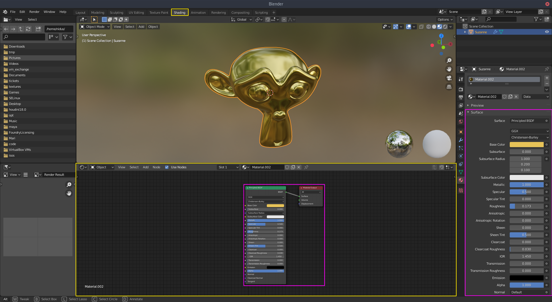
In Blender you can access the Shader Graph by clicking on the Shading Workspace at the top center of Blenders UI.
- Blender Manual Links:
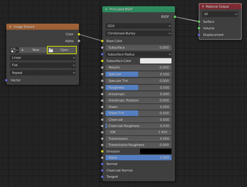
How to apply a simple image texture to the Albedo/Basecolor Slot
To load an image texture (I.e. a bitmap image file like .png or .jpg) we need to create a Image Texture node.
All commands below, especially the Hotkeys assume your mosue cursor is hovering over the Shader Editor.
There is multiple ways to add a Image Texture Node to the Shader Editor:
Drag and drop the image from your filebrowser onto the Shader Editor to automatically create a Image Texture Node that has you texture file already loaded
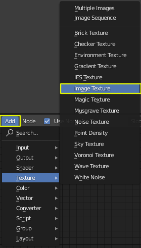
Add >> Texture >> Image Texture or Hotkey: Shift + A >> Texture >> Image Texture
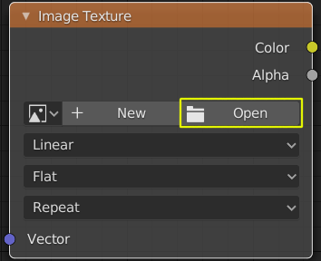
Click Open on the Image Texture Node and select your image file with the filebrowser that pops up
After you have setup your Image Texture Node connect its Color Output to the Principled BSDF’s Basecolor Input.