Lesson 2 - Simple Object Modeling
This time we are modeling simple everyday objects that you got on your desk at home or floating around in your house. We will learn the most often used modeling tools and other basic techniques that will enable you to complete this assignment. We will also check out the Principled BSDF Material a little bit more.
Tip
If you need some inspiration for objects to model check out this Random Object Generator

This assignment is inspired by the amazing photography Carl Kleiner did for Clas Ohlson , FLOS and other floating object photography.
What is a Mesh
A polygonal mesh is made up of vertices, edges and faces. Together they form a 3-dimensional solid object with flat polygonal faces, straight edges and sharp corners (also known as a polyhedron). With these basic building blocks it is possible to create quite complex geometry and there exist algorithms that allow us to subdivide these meshes into smaller polygons to get very smooth looking surfaces.
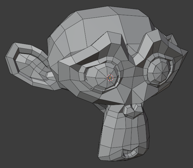
Example of a polygonal mesh (Suzanne blender primitive)
Vertices, Edges, Faces, Polygons
In blender we have the ability to change the topology of a mesh (how the mesh is constructed), by modifiying its vertices, edges, faces (triangles) or polygons (quadrilaterials and ngons). Once we are in Edit Mode we can switch between vertices, edges and faces by pressing the number keys 1,2 and 3. The most common modelling tools we will use in this lesson are described further below in the Modeling Tools section.
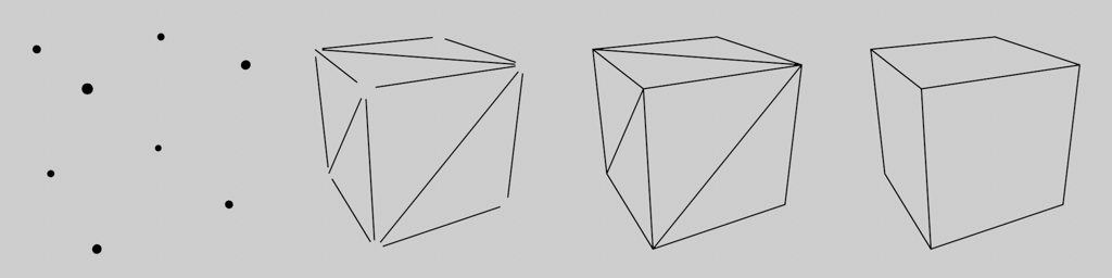
vertices, edges, faces and polygons of a cube
Non-Manifold Objects and problematic Geometry
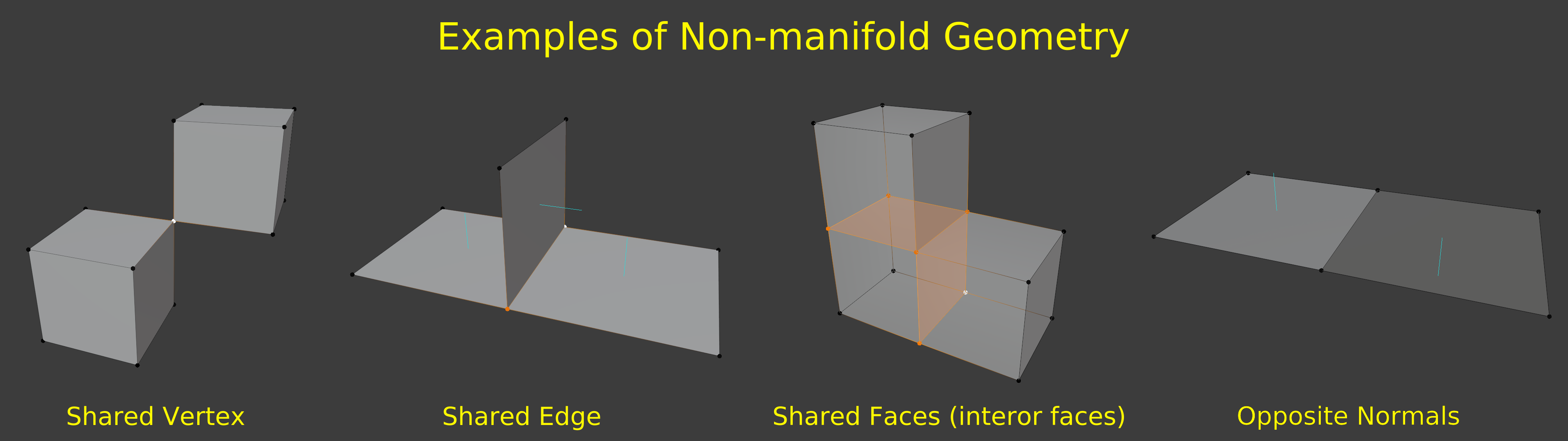
While we create and edit meshes it is possible to create geometry that could lead to problems down the line. Non-manifold geometry for example can’t be unfolded/unwrapped into flat 2D planes during the UV-Unwrapping phase later and might be problematic to texture/paint on. We should avoid creating Non-manifold and other problematic geometry at all cost. You can find examples of Non-manifold geometry below.
Normals
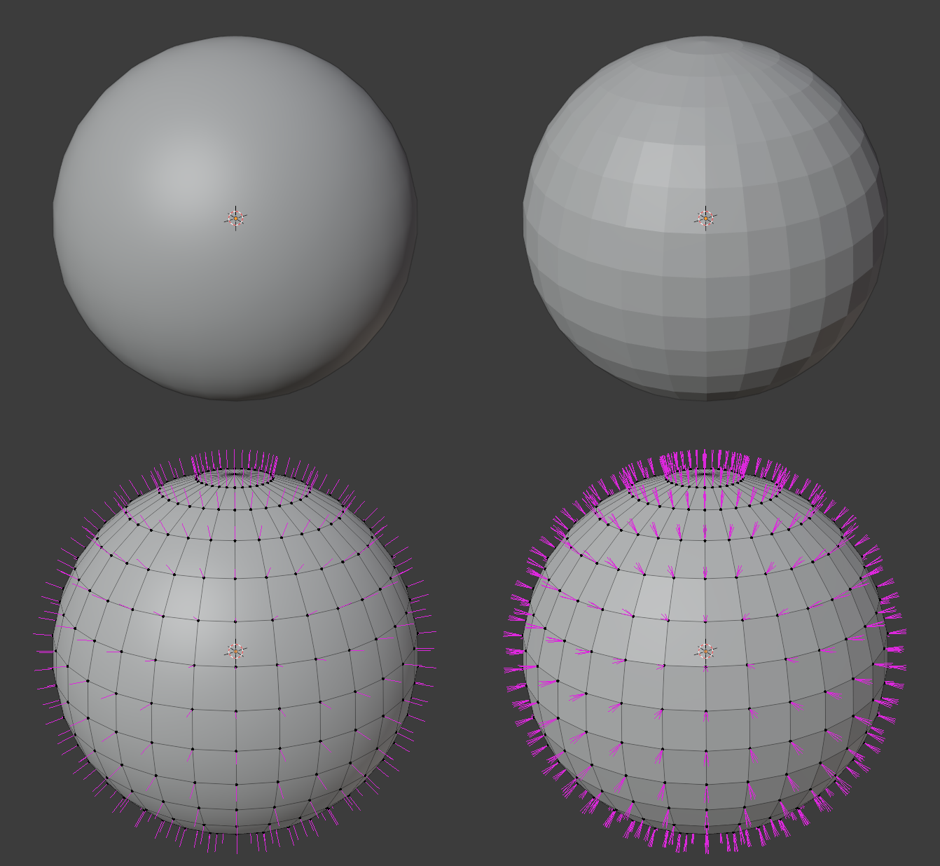
A normal is a vector that is perpendicular to a given object. In our case there are face normals and vertex normals that are perpendicular to the face or vertex they originate from. On a 3D mesh the direction of a normal determines how a polygon or face is shaded and lit and because a face has a front and back, in which direction the face is pointing.
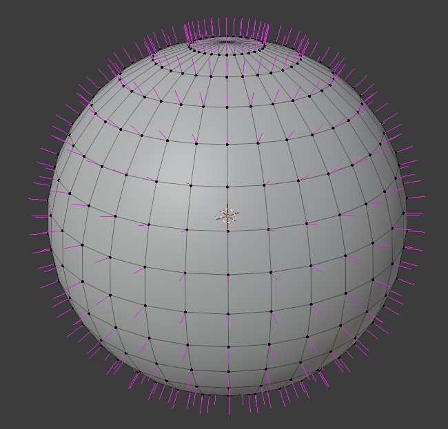
3D Sphere with its smoothed normals displayed in pink
Tip
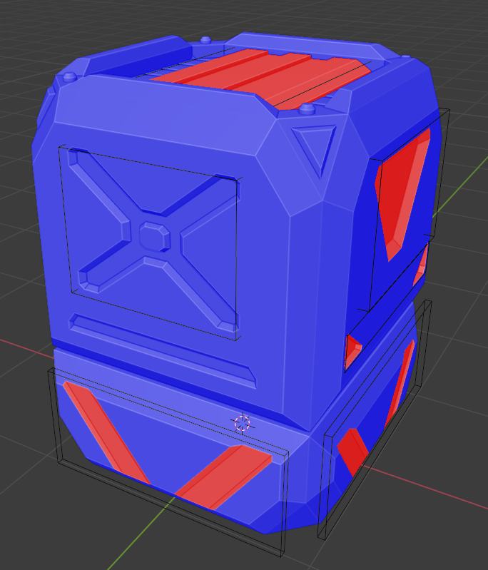
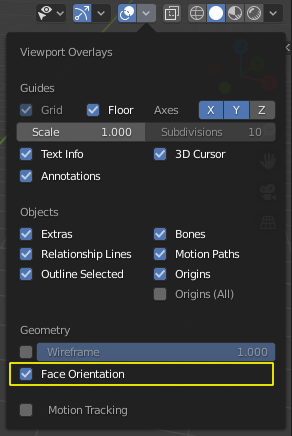
Faces with normals pointing in the wrong direction can be problematic in many cases, so it’s important to check that our faces are “looking” in the proper direction. Blender has a quick overlay view mode that colors a polygons frontface blue and its backface red, which is very useful for finding objects where all faces are pointing inwards.
It can be enabled in the Viewport Overlays Menu in the top right of the 3D Viewport
To flip a faces orientation select it in Edit Mode and press Hotkey: Alt + N and select Flip to reverse its normal. Alternatively you can press Hotkey: Shift + N to let blender try to fix the problematic areas himself.
How Normals affect Shading
As mentioned before the normal is used while shading and lighting a 3-dimensional polygonal mesh. In its simplest form the shading is determined by calculating the dot-product of the lightvector and the surfacenormal at the shading point. The dot-product of two vectors is 1 (Bright/Lit) if the vectors are parallel to each other (the face is facing the light) and it is 0 (Dark/Shadowed) when the vectors are perpendicular to each other.
Changing the vertex normals of a 3D plane will change how it is lit and shaded and might lead to some very weird lighting, as shown in the figure below.
3D Plane lit from above getting shaded differently as its normals (pink) are adjusted
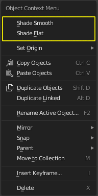
Shade Smooth and Shade Flat
Shade Smooth / Shade Flat >> Hotkey: RMouse in Object Mode
We can also use the fact that normals affect the shading of a 3D mesh to our advantage. By averaging the vertex normals of each face we can fake a smooth surface even though the mesh consists of flat polygons (The silhouette of the mesh will not improve). You can switch between Flat Shading/Faceted Shading and Smooth Shading by Right clicking in Object mode and selecting either from the context menu. This method is very prevalent in games and realtime graphics, which makes it possible to have high fidelity graphics while keeping a lower polygon count.
Auto Smooth
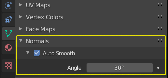
We can also change the normals of a mesh for each edge and define if the normals should be split or averaged/smoothed between the surrounding faces but this is only used when that degree of control is needed for the most part we can use Auto Smooth which is an option that splits or averages the normals based on the angle between the faces.
Selection Tools
Selecting vertices, edges and faces happens often while modeling so we should try to be efficient and quick with it. As always there is more information to be found in the official blender manual linked below this hotkey list.
| Hotkey | Action |
|---|---|
| LMouse | Select vertex, edge, face |
| Shift + LMouse | Add or remove vertex, edge, face from selection |
| Ctrl + LMouse | Point to Point selection |
| Alt + LMouse | Edge/Face Loop Selection |
| Ctrl + Alt + LMouse | Edge/Face Ring Selection |
| A | Select All |
| Alt + A | Deselect All |
| Ctrl + I | Invert current selection |
| Ctrl + Numpad+ | Grow current selection outwards (Select More) |
| Ctrl + Numpad- | Shrink current selection inwards (Select Less) |
| L | Select connected Geometry |
| Alt + Z | X-Ray-Mode (lets you select occluded geometry) |
Tip
Pressing Hotkey: Alt + Z to enter X-Ray-Mode is very useful for selecting different mesh elements (vertices, edges, faces). X-Ray-Mode selects all elements in a rectangular marquee selection box (LMouse-Drag Select). even if they would normally be concealed (I.e blocked/hidden) by other mesh elements.
- Blender Manual Link:
- Blender Manual | Selection
Modeling Tools
Switch between Edit and Object Mode | Hotkey: Tab
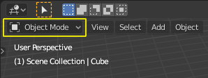
To access the modeling tools and be able to change the topology of the active objects mesh data we have to switch from Object Mode to Edit Mode you can do that by pressing Hotkey: Tab or by using the object interaction mode dropdown in the top left corner of the 3D Viewport. Now you can access all of blenders mesh editing tools, some of which are described below. Once you are done editing the mesh you can press Hotkey: Tab again to go back to Object Mode.
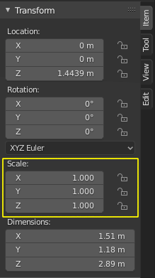
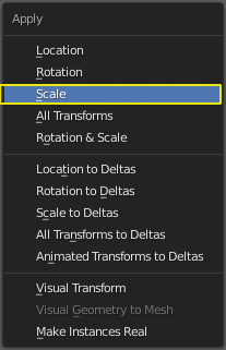
Warning
Some modeling tools may behave very weird if you have been scaling your objects in object mode. That’s because their settings sometimes depend on the object scale. To prevent unexpected results you should use the Apply Scale command to reset the objects scale back to 1.0.
Loop Cut and Slide
Hotkey: Ctrl + R
The Loop Cut tool is a great tool to add additional edges that follow the current topology. It uses the concept of edge and face loops to determine where to cut and gives you the ability to slide the new edge loop around before inserting it. More information on the Loop Cut tool and what exactly face and edge loops are can be found by following the links to the blender manual below.

Tip
- Blender Manual Link:
- Blender Manual | Loop Cut Blender Manual | Select Loops
Knife/Cut
Hotkey: K
The Knife tool is great for cutting arbitrary shapes into the existing geometry. After you have set your cut by left clicking repeatedly confirm the cut by pressing Return/Enter.

- Blender Manual Link:
- Blender Manual | Knife
Bevel
Hotkey: Ctrl + B
The Edge Bevel Tool allows you to round of edges or chamfer them. It’s one of the best tools for smoothing out the very harsh and unnatural edges of our meshes.

- Blender Manual Link:
- Blender Manual | Bevel
Extrude and Inset
Extruding is one of the main ways to add geometry and simultaneously grow our object/mesh into a direction, it works on all mesh components (vertex, edge, face).
Inset is a great to to create slots or prepare geomtry for extrusion. It’s also one of the tools that will be very useful later on when we look at subdivision surface modeling.

- Blender Manual Link:
Deleting and Welding/Merge
We can also simply delete components of the mesh (vertex, edge, face) to create holes or prepare the geomtry for other operations by pressing Hotkey: X
Sometimes we have holes in our meshes or wish to merge together vertices to create spikes or other shapes. The Merge tools let you close meshes or weld together vertices into a single vertex.
- Blender Manual Link:
- Blender Manual | Merge
Closing holes in meshes
In addition to welding vertices we can also close holes in meshes in other ways using other tools. Some of those tools don’t have Hotkeys assigned to them so you can access them via the context dropdown menus in the top left of the 3D Viewport, alternatively you can use the Operator search popup (Hotkey: F3) to search for the operator without having to navigate the menus.
Create Face
Create face will construct a Polygon (Triangle, Quadrilateral or N-Sided Polygon [N-Gon]) from the selected vertices or edges. It is up to you to subdivide large N-Gons in a smart way afterwards to prevent shading issues.

- Blender Manual Link:
- Blender Manual | New Face
Grid Fill
Grid fill will create a geometry patch consisting of multiple faces and will try to shape the patch so it follows the form of the surrounding geometry.
- Blender Manual Link:
- Blender Manual | Grid Fill
Bridge
Bridgeing can be used to close holes in meshes by selecting two groups of vertices or edges. Alternatively you can punch holes into a mesh by selecting two groups of faces and the Bridge tool will delete them and connect their borders.
- Blender Manual Link:
- Blender Manual | Bridge
Principled BSDF Specular
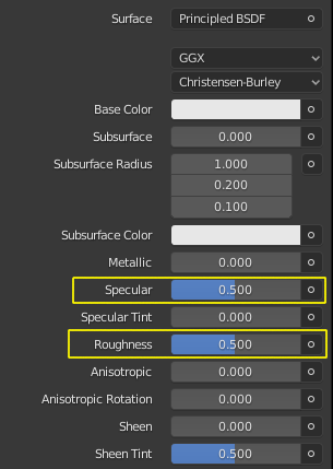
For this assignment you can experiment with the Principled BSDF Materials Roughness and Specular parameters to change the surface look of your material. Roughness affects the surface roughness, a value of 0 will make your material very shiny/glossy while a value of 1 will make it very rough and dull. Specular controls how much the surface reflects light overall, a value of 0 means the material will not reflect anything while a value of 1 will boost the amount of lightreflection the material has. The Default value of 0.5 for the Specular parameter is physically correct for a large amount of Materials.
Material Roughness from 0 (glossy) to 1 (rough)
Material Specular from 0 (no reflection) to 1 (very reflective)
Volume Shader
To get the glowing effect on our light sources without having to place objects with an emission shader we can also place a Volume Shader on our scene to simulate particles/smoke in the air.
Contrary to a Surface Shader (e.g. Principled BSDF) which defines the look of the 3D Mesh Surface a Volume shader works on the Volume of a 3D Mesh (I.e only inside the Mesh)
So we have to create a 3D Mesh that represents our Volume and then assign a Principled Volume Shader to it. Follow these steps to do exactly that (click on the images to see them at full resolution)
Create a Cube primitive [Shift + A >> Mesh >> Cube]
Scale it up so it covers your scene objects and light sources
Select the Cube, open the
 Material Properties in the Properties Panel and add a new Material by clicking on +New
Open the Surface Rollout and click on the Surface Slot and choose Remove on the top right
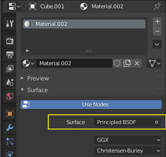
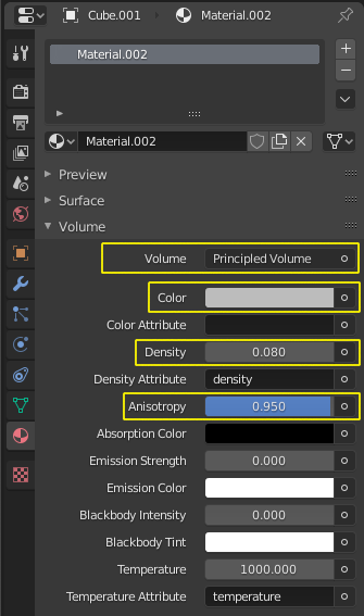
Open the Volume Rollout right below the Surface Rollout, click on the Volume Slot and select the Principled Volume
Go to the
 Render Properties in the Properties Panel on the right side of Blenders UI
and enable Volumetric Lighting in the Volumetric Rollout of Eevee’s Render Properties
Render Properties in the Properties Panel on the right side of Blenders UI
and enable Volumetric Lighting in the Volumetric Rollout of Eevee’s Render Properties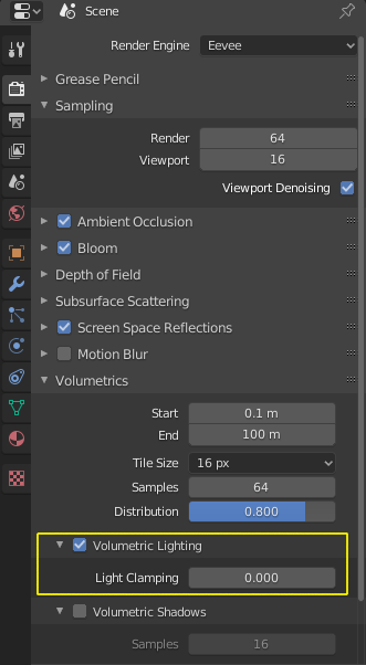
Feel free to experiment with the Settings of the Principled Volume Shader that I highlighted in yellow at step 5 to get different effects or copy mine for a very slight glow.