Lesson 3 - Advanced Modeling
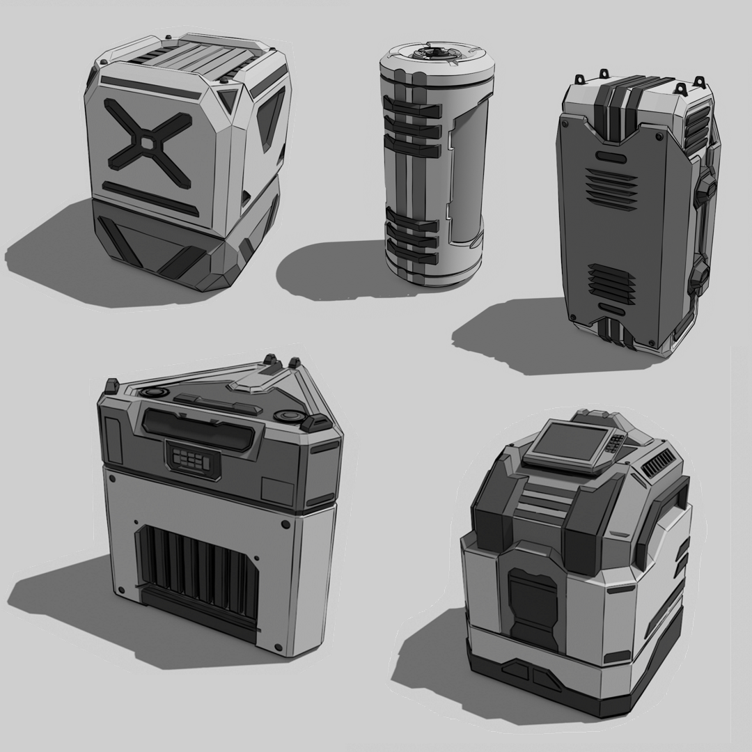
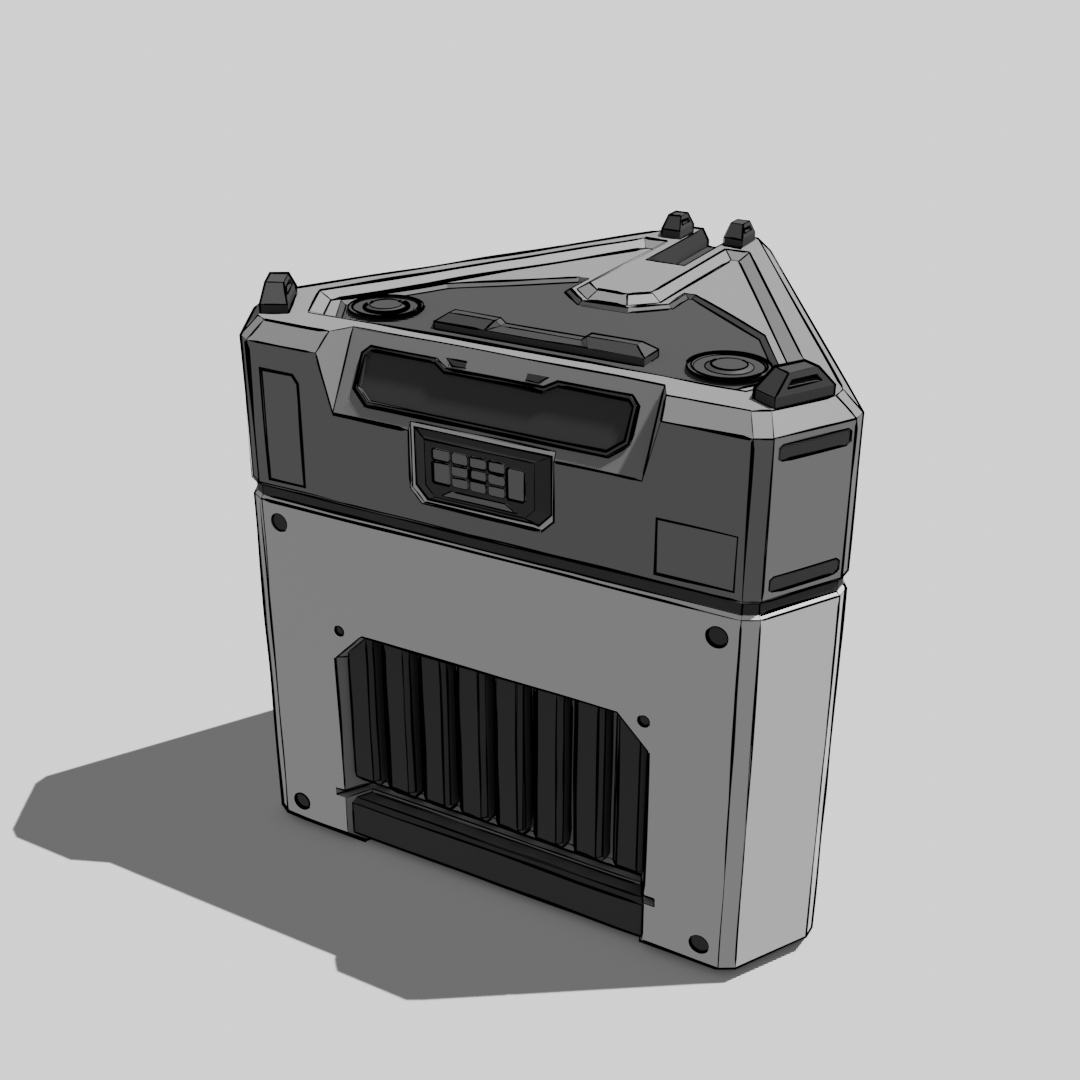
In this lesson we are going to do some concept art, but we are not going to draw, we are going to model it and then render it to look like concept art. The goal is to create 5 Scifi-Container designs using the methods and techniques shown in this lesson and listed below. An example of how the end result can look like just below this text.
We will be looking at following topics:
- 3D Topics
- Basic Scene Management with collections
- Non-destructive / Procedural Modelling techniques
- Constructive Solid Geometry (CSG/Booleans)
- Freestyle line rendering
- Design Theory
- Big, Medium, Small
- Gestalt Principles
- Dynamic Symmetry and Rule of thirds
3D Topics
Collections / Groups
We can use collections to organize our blender scene and group multiple objects that belong together. You can navigate your scenes Collections in the Outliner at the top right in the Blender UI. To add objects to a collection simply Drag and Drop them onto the Collection in the Outliner.
To make sure all newly created objects are automatically added to the collection you want click on the box icon next to the name of the collection to make it the active collection (In the image below the Crate_03 Collection is active)
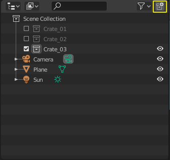
Blender Outliner with the button to create a new collection highlighted in yellow
Tip
You can also add objects to a collection by selecting them in the Outliner or 3D Viewport and pressing Hotkey:M to open a floating context menu next to your mousecursor with a list of all collections in the file and click on the collection name.
- Blender Manual Link:
- Blender Manual | Collections
Non-destructive / Procedural Modelling (Modifiers)
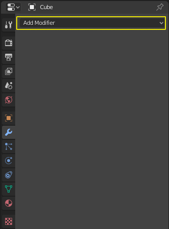
Modifier Panel for a cube object
While all the changes to the mesh we have been doing in edit mode are final and are hard to change once we exit the modeling tool, there are other ways to modify geometry that keep the operations adjustable. This way of modelling is often referred to as Procedural Modelling or Non-destructive Editing because we can change the parameters of the modeling operators at any time.
Blender uses Modifiers which can be added to objects to implement this
functionality. The  Modifier Panel in the Properties
Panel on the right hand side of Blenders UI lets you add modifiers to the
currently active object.
Modifier Panel in the Properties
Panel on the right hand side of Blenders UI lets you add modifiers to the
currently active object.
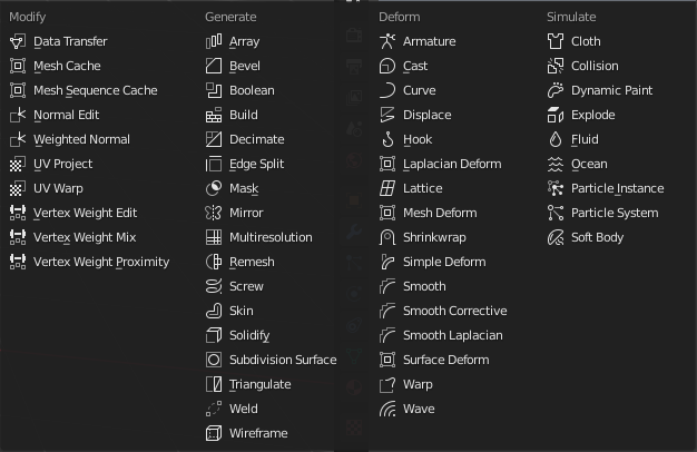
List of all available modifiers in blender
We will use the following modifiers in this lesson:
- Mirror
- Boolean
- Solidify
- Bevel
- Subdivision Surface
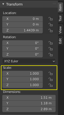
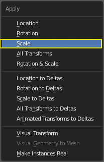
Warning
Some modifiers may behave very weird if you have been scaling your objects in object mode. That’s because their settings sometimes depend on the object scale. To prevent unexpected results you should use the Apply Scale command to reset the objects scale back to 1.0.
- Blender Manual Link:
- Blender Manual | Modifiers
Constructive Solid Geometry
Constructive Solid Geometry or CSG for short, describes the process of creating complex geometry from simple solid primitives by subtracting, adding or intersecting their volumes. Often this process is called Booling or Boolean operation because the process of subtracting, adding or intersecting is often expressed as typical mathematical boolean operations (NOT, OR, AND, XOR, …).
In Blender the CSG/Boolean modifier features the following boolean operations:
- Difference (Boolean NOT)
- Union (Boolean OR)
- Intersection (Boolean AND)
| Boolean Union (∪) | Boolean Difference (-) | Boolean Intersection (∩) |
|---|---|---|
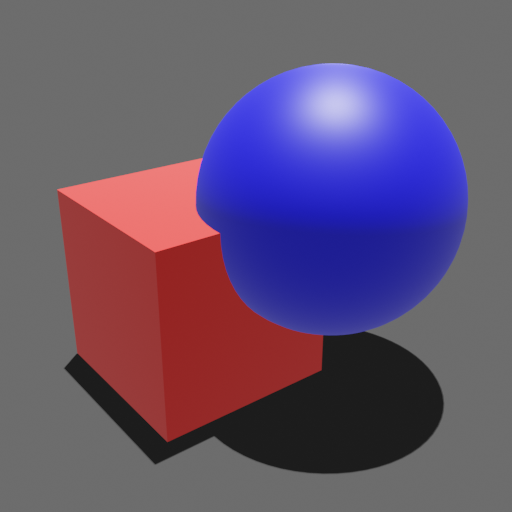 |
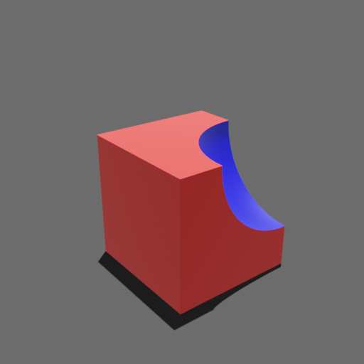 |
 |
| Union of Cube and Sphere | Difference of Cube and Sphere | Intersection of Cube and Sphere |
With these simple boolean operations it is possible to construct very complicated geometry while combining very simple building blocks. Multiple CSG operations can be displayed as a binary tree like in the figure below. The resulting geometry is shown at the top while it’s operands and boolean operations are shown as leaves (Cylinder, Cube, Sphere) and nodes (Union, Difference, Intersection).
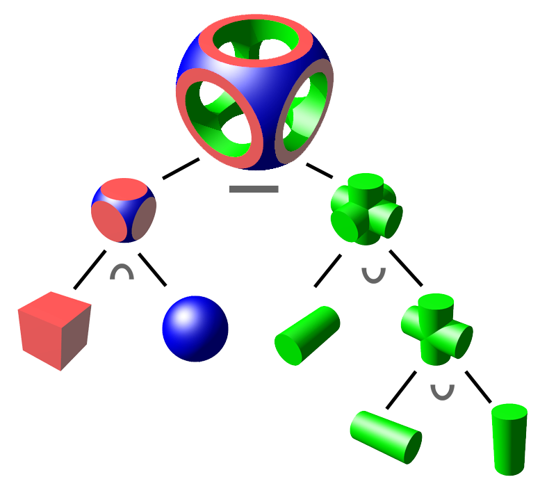
Example of complex geometry constructed from simple solid primitives (Wikimeda Commons: Zottie)
Warning
Boolean operations work only on solid objects, meaning closed 3D Meshes without holes and their normals pointing in the right directions (inward). If a Boolean operation fails check your Operands for holes or unwelded vertices.
How it works in Blender
Boolean operations are implemented as a blender modifier. The modifier is simply called Boolean.
Here is the step by step process to create a boolean operation between a cube and a sphere:
Create a cube (Shift + A >> Mesh >> Cube) [Operand A]
Create a sphere (Shift + A >> Mesh >> Sphere) [Operand B]
Select the cube, it will act as our stock (Operand A)
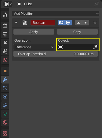
- Add a Boolean modifier in the Modifier PropertiesThe Modifier Properties are located at the right hand side in the Properties Panel
Add the boolean modifier to the cube (Add Modifier >> Boolean)
Use the Object: Eyedropper tool in the modifier gui to select the sphere as a cutter
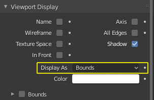
Select the Sphere in the 3D Viewport and open the Object Properties

Navigate to the Viewport Display Rollout and set the spheres display to Bounds
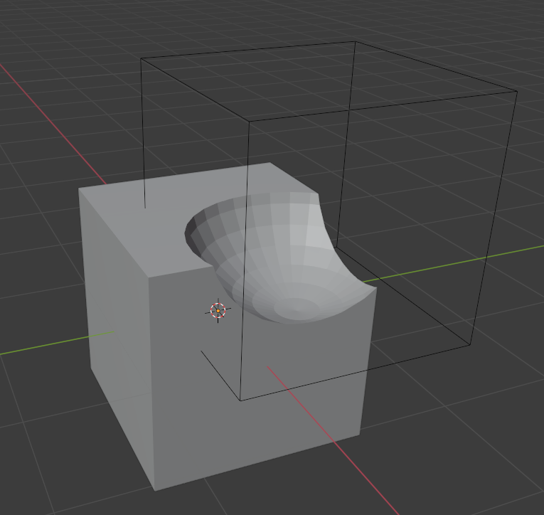
Now you can manipulate your Sphere (Cutter/Operand B) by selecting its bounds and transforming it and the boolean operation will update accordingly.
The result should look something like this:
Warning
Your Cutter object will still be visible when you Render your final image (Hotkey: F12) to get control over which objects will show up in the final render you need to enable the Disable in Render Flag in the Outliner Filter Menu (Shown below).
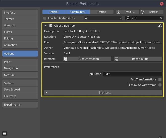
A faster and more convenient way to work with booleans
There is an addon that ships with blender that makes all of this way easier. Its called Bool Tool and you can find it in the Preferences >> Add-Ons.
After activating the addon you can call it’s menu by pressing Hotkey: Ctrl + Shift + B
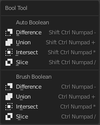
The process for booling a cube and a sphere is now way faster and easier:
- Select the sphere (Operand B / The Cutter)
- Select the cube (Operand A / The Stock)
- Press Ctrl + Shift + B
- Select the appropriate boolean operation from the menu
Note
Brush Boolean keeps the boolean operation interactive and you can still move the cutter while Auto Boolean will apply the boolean and only leave the resulting mesh behind. Therefore only choose Auto Boolean if you are sure you don’t want to tweak the result.
Material Slots and Boolean modifiers
During the boolean operation with Operand A and Operand B some attributes that are set on Operand B (Cutter) will be transferred over to the geometry the boolean operation creates on Operand A. That means the resulting faces will carry over the Material, Normals and some other attributes of Operand B. With this we can not only cut away or add to our Designs but also simultaneously assign materials to specific areas of the resulting mesh.
For this to work we have to make sure there are Material slots on our Stock / Operand A Object.
To add a material slot you can press the Button with the + symbol in the  Material Properties Panel (Highlighted in Yellow in the image below)
You can also apply specific Materials to selected Faces in Edit Mode by selecting it in the SlotList (Highlighted in Blue) and then clicking on the Assign-Button (Highlighted in Red, only visible in Edit Mode).
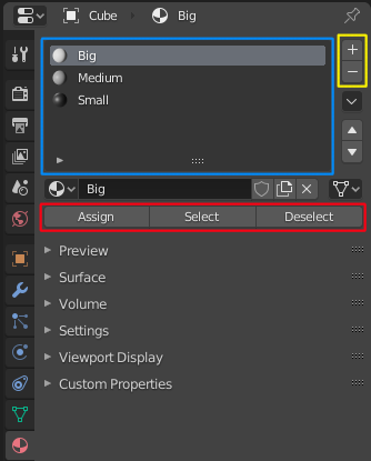
MaterialSlot-List (Blue), Add/Remove Materialslot button (Yellow) and Edit Mode Buttons (Red)
Tip
For our Big, Medium, Small Color coding with White, Grey, Darkgrey to work we will have to setup our Material Slots exactly like in the image above on our Operand A (Stock Object). And then have a single material on our Operand B that matches it’s Size (Big, Medium, Small) and it will carry over and be shaded correctly.
Video showing how to assign materials to different faces in edit mode:
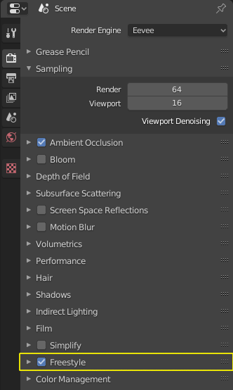
Freestyle Line Renderer
Blenders Freestyle line renderer lets you create Non-Photorealistic-Renders (NPR). It is very customizable and has a huge amount of parameters you can tweak to create very unique looking lineart, that can look very close to a handdrawn style. We will be using very basic settings to achieve the look in the image below, but feel free to experiment.
To activate the Freestyle Renderer open the  Render Properties Panel
in the Properties Panel on the right hand side and scroll down to the Freestyle Rollout
and tick the checkbox.
Render Properties Panel
in the Properties Panel on the right hand side and scroll down to the Freestyle Rollout
and tick the checkbox.
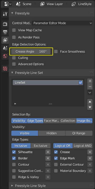
All settings for the Freestyle Renderer are in the  Viewlayer Properties
in the Properties Panel at the very bottom of the Viewlayer Panel. I recommend bumping the
Crease Angle setting up to 160 Degrees so even very shallow changes in geometry are getting
drawn as outlines.
Viewlayer Properties
in the Properties Panel at the very bottom of the Viewlayer Panel. I recommend bumping the
Crease Angle setting up to 160 Degrees so even very shallow changes in geometry are getting
drawn as outlines.
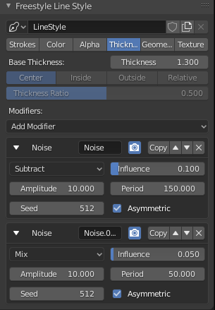
To Match the look of my example you can adjust your settings until they reflect those in the screenshots below.
Hint
If the line width modulation doesn’t look right in your scene it might be because you are working at a different scale than me. You can adjust the width modulation by changing the Period of the Noise Modifiers to bigger or smaller values. Smaller values will make the changes in line width more abrupt will larger values will make the changes more subtle and smooth.
The first and second noise modifier are using periods in a ratio of 3 to 1 (150 to 50). If you want to keep the look adjust them but keep the ration the same (i.e 60 to 20 or 300 to 100)
If the width modulation isn’t strong enough you can play with the Influence Sliders.
Design Theory
Big, Medium, Small (Primary, Secondary, Tertiary)
Big, Medium, Small or Primary, Secondary, Tertiary Shapes or 1st, 2nd, 3rd Read are all names for the way we can structure our designs to make it easier to understand, more pleasing to the eye and more interesting. It’s what makes a design interesting, cool or satisfying to look at, if it is applied correctly and in conjunction with the other principles explained below.
Ratio at which the Elements should occur
This design theory also dictates at which ratio the Big, Medium and Small Elements should appear in relation to each other.
This ratio can vary a little bit but most of the time it is 70/30 or 80/20. For example the Big shape takes up 70% of the design while the medium sized shape takes up 30%. Continuing with this the Small Shapes take up 30% of the space the Medium Shapes leaving 70% uncluttered.
Variation and Clustering
Too much of the same shape is boring, so try to have variation in the size of the shapes in all three categories (Big, Medium, Small). When you place a lot of small shapes, instead of positioning them evenly spaced try to cluster them together in groups while leaving some larger spaces between them for a more pleasing design.
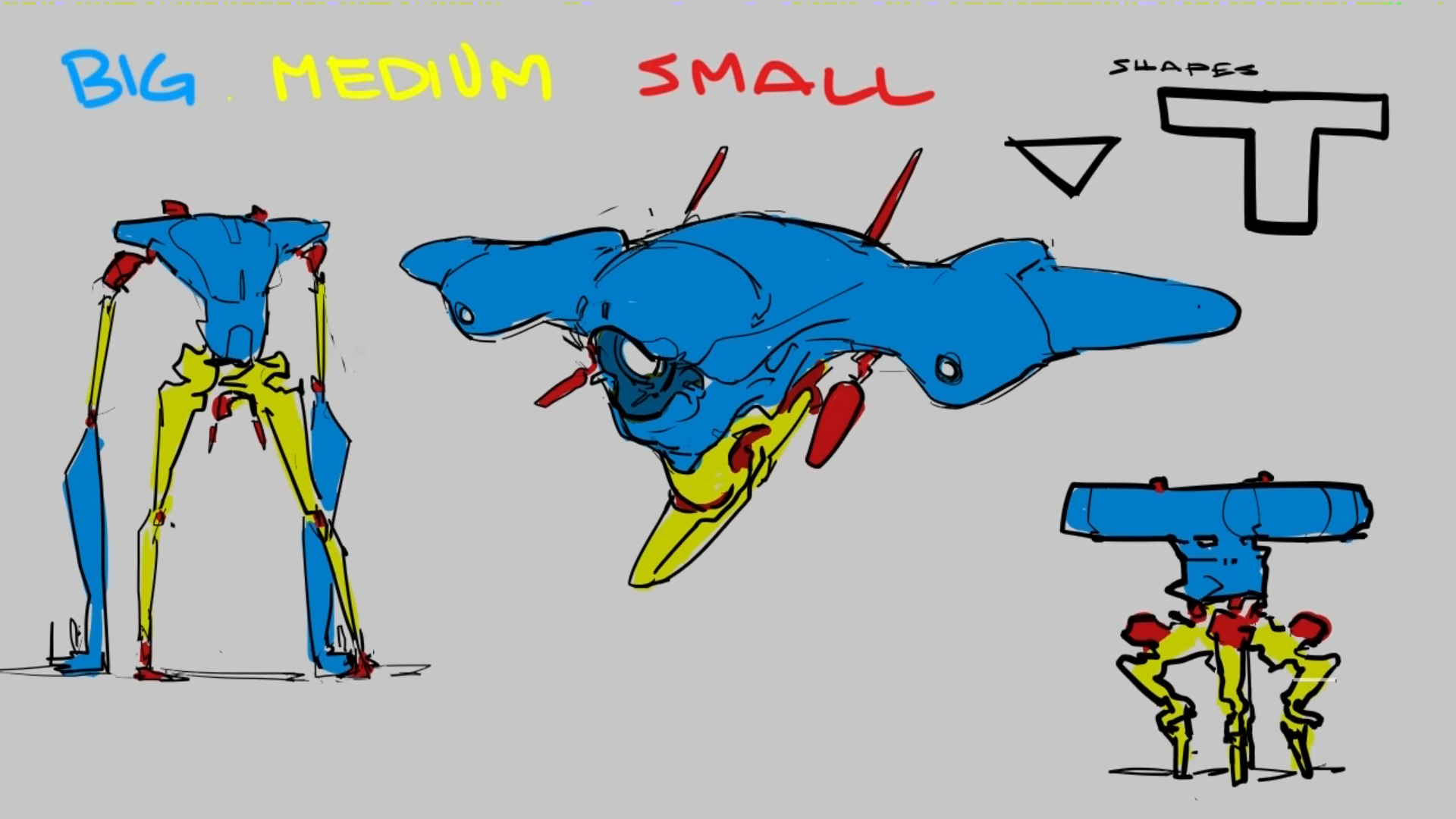
Example of color coded designs (Big, Medium, Small | White, Grey, Black | Blue, Yellow, Red)
- Further Reading/Watching:
- https://www.youtube.com/watch?v=ZluGXgpdJj4
- https://www.linodriegheart.com/design-principles-in-concept-art-and-design/
- http://neilblevins.com/cg_education/primary_secondary_and_tertiary_shapes/primary_secondary_and_tertiary_shapes.htm
- https://www.youtube.com/watch?v=6IojuePYIHo
- https://www.youtube.com/watch?v=qMH_J_vcoqE
Gestalt Principles/Psychology
The Gestalt Principles/Psychology is a school of psychology that first emerged in Germany and Austria in the early 1900s. It was opposed to the dominant view of structuralism that ruled the field of psychology in that time. With the help of test and experiments the psychologists came up with a set of rules for perception which are listed below.
Instead of long explanations I tried to keep the rules to one liners with one or two example images. If you want to read more on the subject there are links for further reading at the bottom of this section.
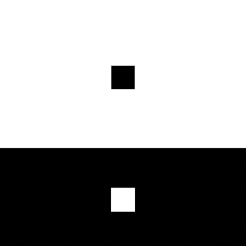
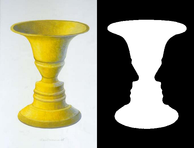
Figure-Ground Relationship
How we perceive an object is determined by the relationship of the object or figure to its background. Good Figure-Ground Relationship most of the time means good readability of shapes/objects/characters.
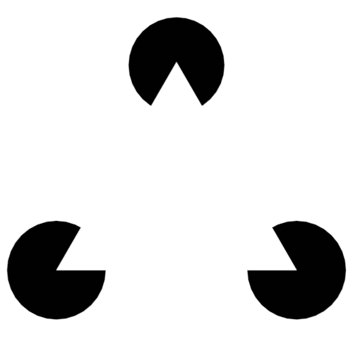
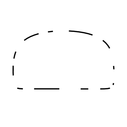
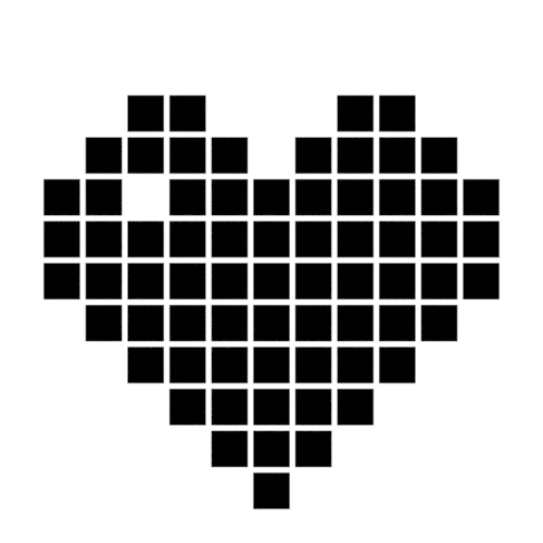
Law of Closure
We favor closing incomplete shapes instead of seeing their parts as their own shapes.

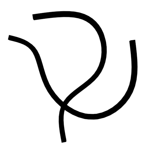
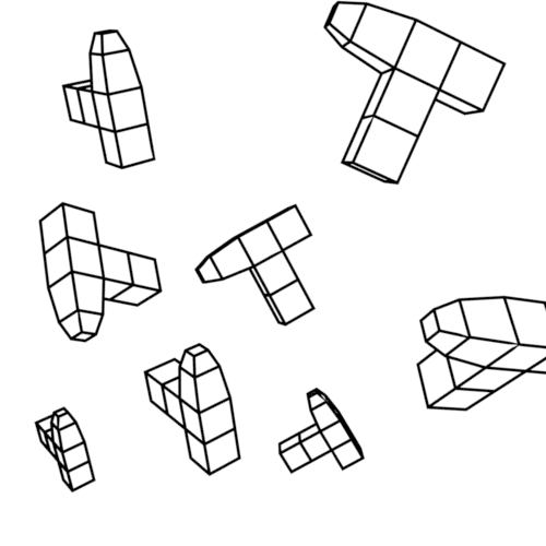
Law of Continuity
Lines or Curves that aren’t complete will be automatically completed in our brains. An X shape will be interpreted as two crossing lines not two bent/kinked lines.


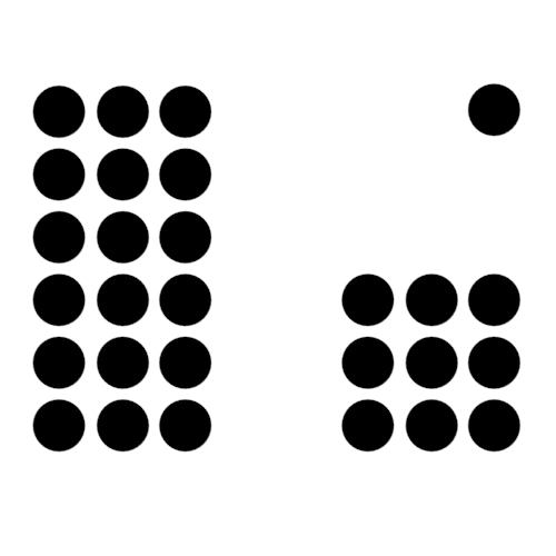
Law of Similarity
Elements who are similar to each other will more likely be perceived as as belonging together.

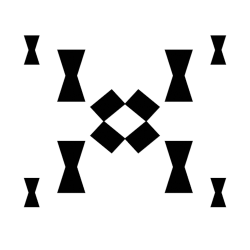
Law of Symmetry
We perceive objects as being symmetrical and forming around a center point. It is pleasing to the eye to divide objects into symmetrical parts, we also perceive unconnected objects as symmetrical to a point or axis if possible.

Dynamic Symmetry and Rule of Thirds
These two theories are used to help you compose a shot/painting/scene. They come with rules or grids that you can use to align objects inside your cameraview to get a more pleasing composition.
The Rule of thirds can be a stepping stone and an okay helper in the beginning but truly great composition uses a lot more rules/guides. Dynamic symmetry steps in here with a more complex grid that helps create more pleasing images because its grid follows other very important rules.
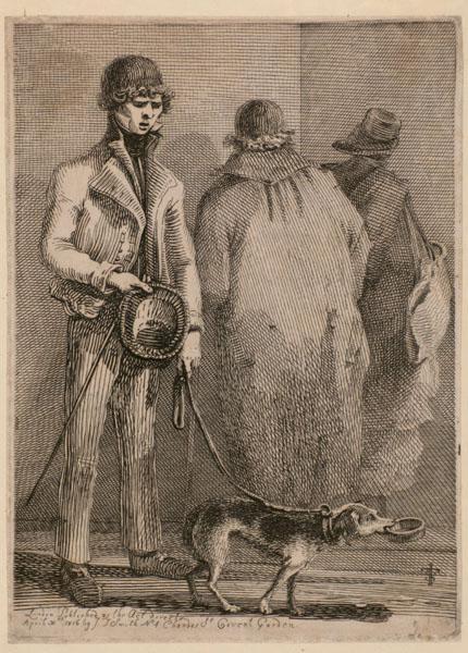
Rule of Thirds
John Thomas Smith (1766-1833) [English painter, engraver and antiquarian] came up with the rule of thirds in 1797. By splitting the Image into thirds with four lines a simple grid is created. It is claimed that positioning your subject on one of the power points (the intersections of the gridlines) or close to it will create more interest and a better composition than shooting your subject dead center.
You can get good artwork with the rule of thirds if you use additional other principles, but if you only focus on the rule of thirds you are limiting yourself and your art.
Warning
The rule of thirds is not in this list because it is a good tool or something I want you to use. It’s here as a bad example, as an example of how oversimplifying something complex like composition can lead to bland artwork. It’s better than nothing, thats for sure, but it’s a dead end composition wise, it will not lead you anywhere after your first improvements.
Example: John Thomas Smith

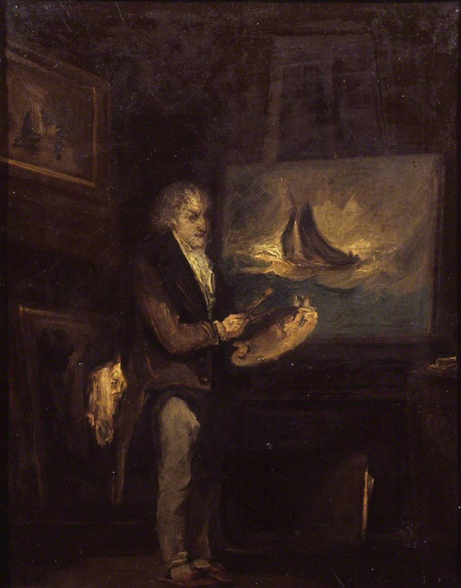
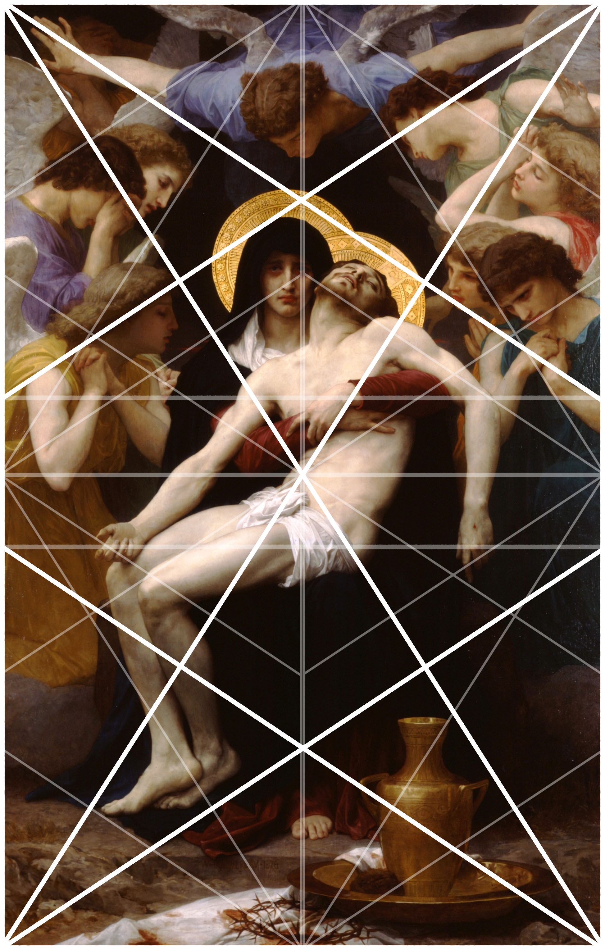
Dynamic Symmetry
Dynamic Symmetry was formulated by Jay Hambidge (1867-1924) and is a system defining compositional rules inspired by Greek architecture, sculpture and ceramics.
It’s most useful part is the dynamic symmetry grid which can be used to arrange objects in our scene/frame.
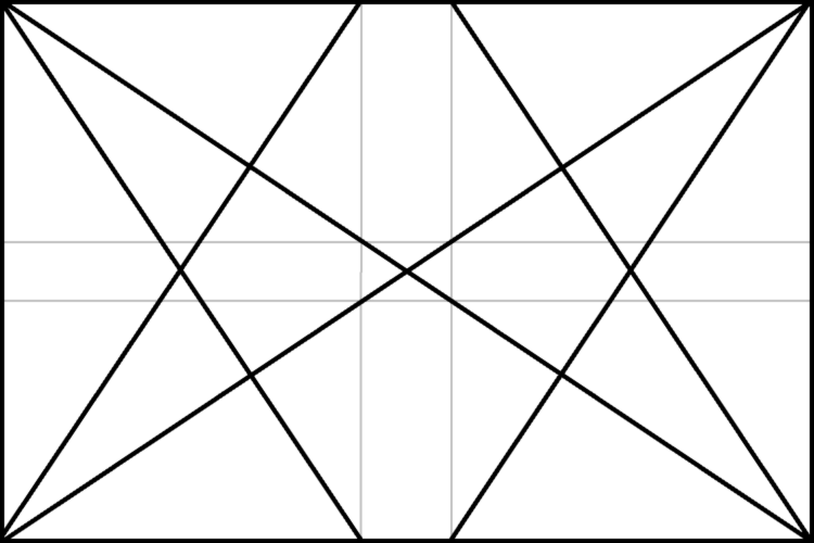
Dynamic symmetry grid for a 1.5 Rectangle (typical film camera sensor aspect ratio)
- The dynamic symmetry grid has the following parts:
- Baroque diagonal (lower left to upper right)
- Sinister diagonal (lower right to upper left)
- The Reciprocals (crossing the sinister and baroque at 90 degree angles)
- The Eyes (points where lines are crossing)
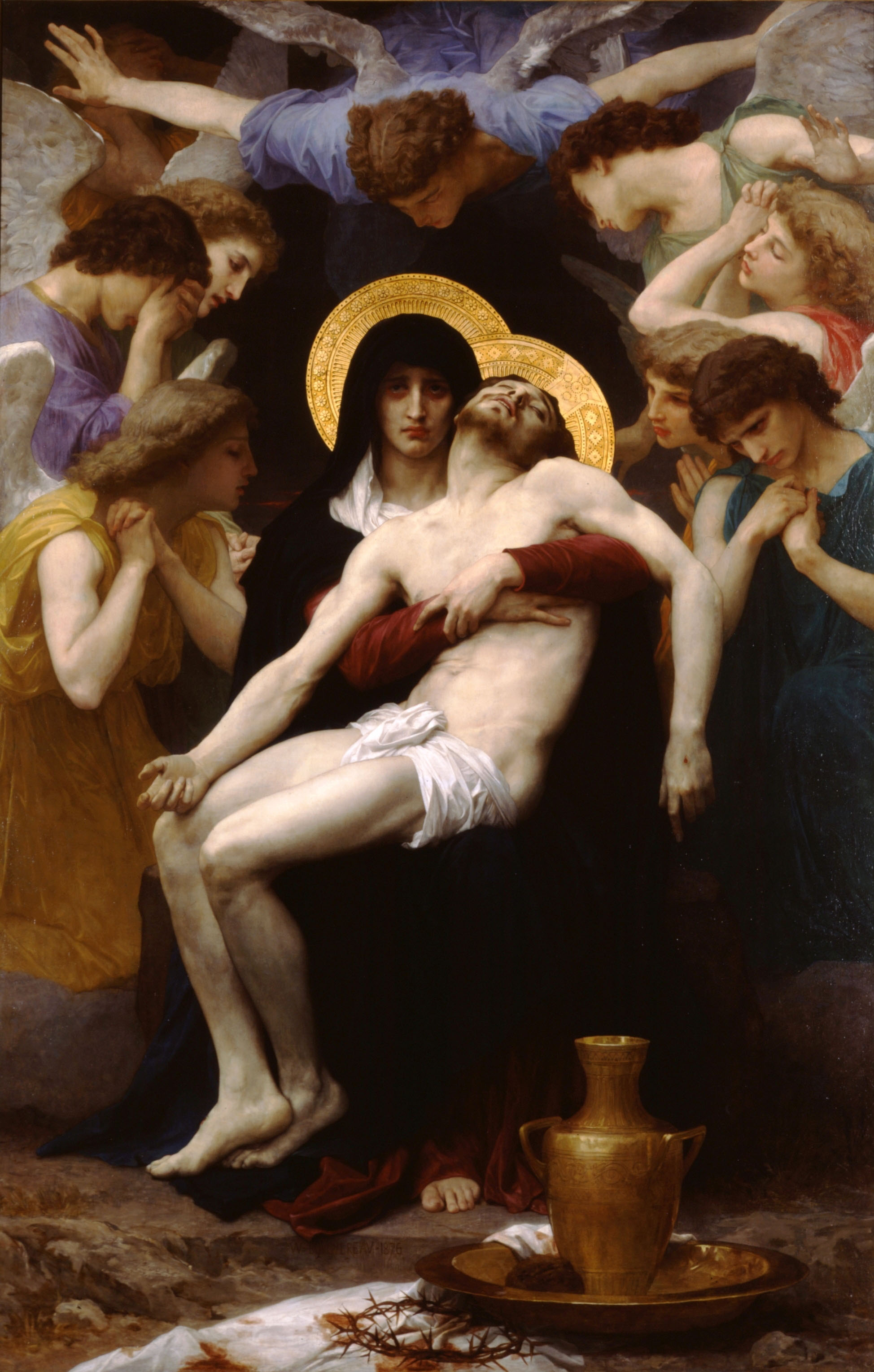
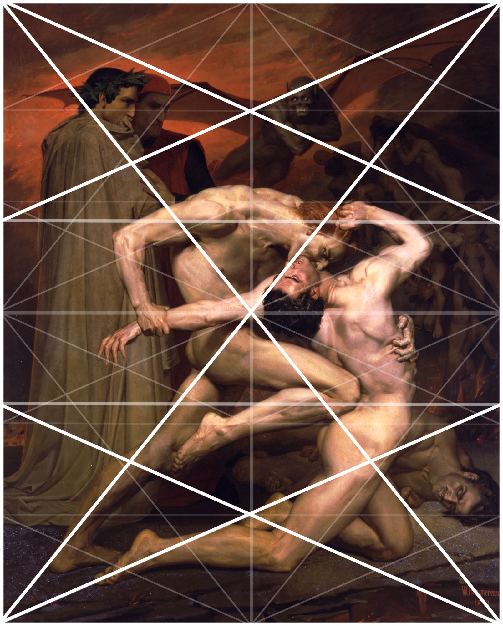
In a process called Major Area Division (MAD) we can use multiple shrinked down dynamic symmetry grids to get even more lines to align our subjects to. Major Area Subdivision is shown below in the third image.
Example: William-Adolphe Bouguereau - Pieta (1876)

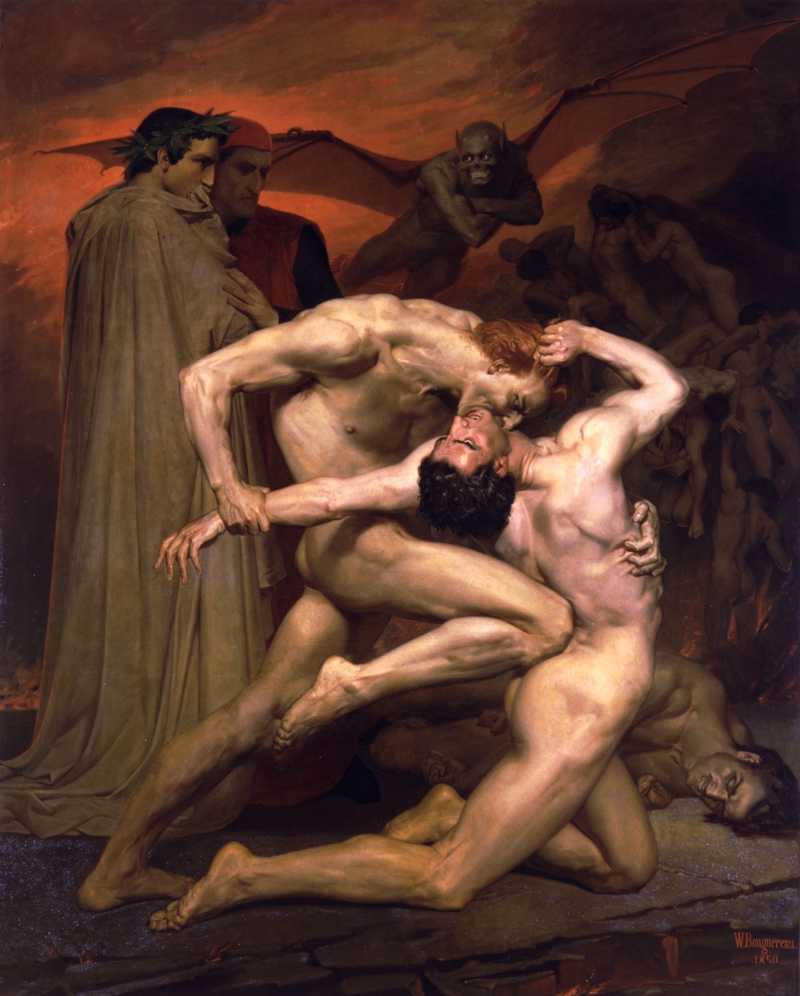
Example: William-Adolphe Bouguereau - Dante and Virgil in Hell (1850)

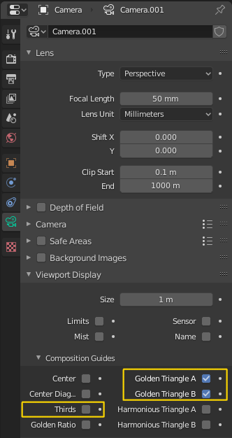
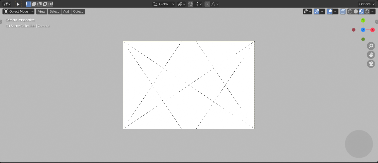
Grids in Blender
You can enable the rule of thirds grid and the dynamic symmetry grid in Blender
by selecting your Camera and navigating to the  Object Data
Panel in the Properties Panel on the right hand side of Blenders UI.
Open the Viewport Display Rollout and then expand the Composition Guides
Subrollout to find a series of checkboxes that will give you access to different
grids. Once checked the grid will be drawn in the 3D Viewport if you are looking through
the camera.
Object Data
Panel in the Properties Panel on the right hand side of Blenders UI.
Open the Viewport Display Rollout and then expand the Composition Guides
Subrollout to find a series of checkboxes that will give you access to different
grids. Once checked the grid will be drawn in the 3D Viewport if you are looking through
the camera.